Some people requested it, so here it is…
We want to use a 4×20 caracters Arduino LCD on the Raspberry Pi.
We will use the I²C protocol and a small python class to access the display.
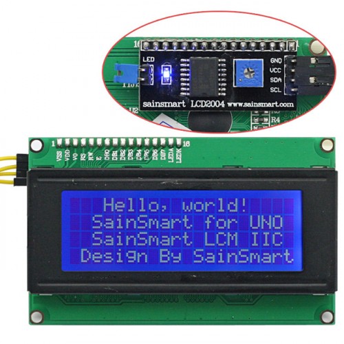
As you can see in this picture, the LCD display has an included I²C board.
Wiring is based on our add a RTC clock previous tutorial . The two modules (RTC and display) could be used in pair, thanks to the I²C protocol. You could even chain more I²C devices.
Be carefull with the logic levels :
Our precious Raspberry Pi works with a 3.3V logic. The display is a 5V logic device. When the Pi’s I²C internal pull-ups are ok for the RTC clock, those won’t be enough to handle the display.
So, we’ll use a small I²C logic converter. It will be very usefull for our future projects, because it allows using 3.3V and 5V devices without worrying about I²C logic levels. A ready-to-use converter costs only a few cents, so it’s a very nice component to add to the Pi.
Edit – 07-09-2015 : The github library has been updated to support backlight toggling !
1- What you need
– a 4×20 I²C display (like this one)
– a 70 cents I²C 3.3v-5v logic converter (like this one)
2- Wiring
Let’s start from the converter :
5V side :
AVCC -> Pi +5v
AVCC -> display +5v
AGND -> Pi GND
AGND -> display GND
ASCL -> display SCL
ASDA -> display SDA
3.3V side :
BVCC -> Pi +3.3v
BGND -> Pi GND
BSCL -> Pi SCL
BSDA -> Pi SDA
With this wiring, one could add I²C devices, without worrying about logic levels : 5V modules connect to the converter’s A side, 3.3V modules connect to the B side. Easy.
2- Enable and setup the I²C in Raspbian
We add the modules to the startup : :
sudo nano /etc/modules
Add those 2 lines:
i2c-bcm2708
i2c-dev
We reboot :
sudo reboot
we now install the required components :
sudo apt-get install python-smbus i2c-tools
We remove the I²C modules from the blacklist :
sudo nano /etc/modprobe.d/raspi-blacklist.conf
the line
blacklist i2c-bcm2708
becomes
#blacklist i2c-bcm2708
Our Raspberry should be ready to use I²C devices after a new reboot.
sudo reboot
3- Testing the I²C
We are going to use the i2cdetect command to list every I²C devices. This command is not the same on a Rev 1 or Rev 2 Pi (I²C bus address is different), so it’s important to choose the right one :
sudo i2cdetect -y 0 (for Rev 1)
sudo i2cdetect -y 1 (for Rev 2)

On this screenshot, you can see my Pi has 3 I²C devices :
– display with address #27
– unused AT24C32 eeprom chip with address #50
– DS1307 RTC with address #68. It is noted « UU » because it’s in use.
Your display may have another address. I’ve seen #24 and #28 but it can be something else. It should be indicated in the display’s datasheet. We need this address to setup the driver a little later.
4- Python class install
To ‘talk’ with the display, we will use a small python class. So, the prefered language to use the display will also be python.
Let’s create 2 files in a subfolder of the home directory, and copy-paste the content in each one
cd
mkdir display_420
sudo nano i2c_lib.py
import smbus
from time import *

class i2c_device:
   def __init__(self, addr, port=1):
      self.addr = addr
      self.bus = smbus.SMBus(port)

# Write a single command
   def write_cmd(self, cmd):
      self.bus.write_byte(self.addr, cmd)
      sleep(0.0001)

# Write a command and argument
   def write_cmd_arg(self, cmd, data):
      self.bus.write_byte_data(self.addr, cmd, data)
      sleep(0.0001)

# Write a block of data
   def write_block_data(self, cmd, data):
      self.bus.write_block_data(self.addr, cmd, data)
      sleep(0.0001)

# Read a single byte
   def read(self):
      return self.bus.read_byte(self.addr)

# Read
   def read_data(self, cmd):
      return self.bus.read_byte_data(self.addr, cmd)

# Read a block of data
   def read_block_data(self, cmd):
      return self.bus.read_block_data(self.addr, cmd)
sudo nano lcddriver.py
import i2c_lib
from time import *

# LCD Address
ADDRESS = 0x27

# commands
LCD_CLEARDISPLAY = 0x01
LCD_RETURNHOME = 0x02
LCD_ENTRYMODESET = 0x04
LCD_DISPLAYCONTROL = 0x08
LCD_CURSORSHIFT = 0x10
LCD_FUNCTIONSET = 0x20
LCD_SETCGRAMADDR = 0x40
LCD_SETDDRAMADDR = 0x80

# flags for display entry mode
LCD_ENTRYRIGHT = 0x00
LCD_ENTRYLEFT = 0x02
LCD_ENTRYSHIFTINCREMENT = 0x01
LCD_ENTRYSHIFTDECREMENT = 0x00

# flags for display on/off control
LCD_DISPLAYON = 0x04
LCD_DISPLAYOFF = 0x00
LCD_CURSORON = 0x02
LCD_CURSOROFF = 0x00
LCD_BLINKON = 0x01
LCD_BLINKOFF = 0x00

# flags for display/cursor shift
LCD_DISPLAYMOVE = 0x08
LCD_CURSORMOVE = 0x00
LCD_MOVERIGHT = 0x04
LCD_MOVELEFT = 0x00

# flags for function set
LCD_8BITMODE = 0x10
LCD_4BITMODE = 0x00
LCD_2LINE = 0x08
LCD_1LINE = 0x00
LCD_5x10DOTS = 0x04
LCD_5x8DOTS = 0x00

# flags for backlight control
LCD_BACKLIGHT = 0x08
LCD_NOBACKLIGHT = 0x00

En = 0b00000100 # Enable bit
Rw = 0b00000010 # Read/Write bit
Rs = 0b00000001 # Register select bit

class lcd:
   #initializes objects and lcd
   def __init__(self):
      self.lcd_device = i2c_lib.i2c_device(ADDRESS)

      self.lcd_write(0x03)
      self.lcd_write(0x03)
      self.lcd_write(0x03)
      self.lcd_write(0x02)

      self.lcd_write(LCD_FUNCTIONSET | LCD_2LINE | LCD_5x8DOTS | LCD_4BITMODE)
      self.lcd_write(LCD_DISPLAYCONTROL | LCD_DISPLAYON)
      self.lcd_write(LCD_CLEARDISPLAY)
      self.lcd_write(LCD_ENTRYMODESET | LCD_ENTRYLEFT)
      sleep(0.2)

   # clocks EN to latch command
   def lcd_strobe(self, data):
      self.lcd_device.write_cmd(data | En | LCD_BACKLIGHT)
      sleep(.0005)
      self.lcd_device.write_cmd(((data & ~En) | LCD_BACKLIGHT))
      sleep(.0001)

   def lcd_write_four_bits(self, data):
      self.lcd_device.write_cmd(data | LCD_BACKLIGHT)
      self.lcd_strobe(data)

   # write a command to lcd
   def lcd_write(self, cmd, mode=0):
      self.lcd_write_four_bits(mode | (cmd & 0xF0))
      self.lcd_write_four_bits(mode | ((cmd << 4) & 0xF0))

   # put string function
   def lcd_display_string(self, string, line):
      if line == 1:
         self.lcd_write(0x80)
      if line == 2:
         self.lcd_write(0xC0)
      if line == 3:
         self.lcd_write(0x94)
      if line == 4:
         self.lcd_write(0xD4)

      for char in string:
         self.lcd_write(ord(char), Rs)

   # clear lcd and set to home
   def lcd_clear(self):
      self.lcd_write(LCD_CLEARDISPLAY)
      self.lcd_write(LCD_RETURNHOME)
In this lcddriver.py file, you’ll have to set the I²C address. It defaults to #27 :
# LCD Address
ADDRESS = 0x27
5- Using the display
It’s the fun part…
If you want to use the display in a python script, you only have to include those 2 files your script folder.
Here is what you need to use it in you script :
# loading the class
import lcddriver
from time import *

# lcd start
lcd = lcddriver.lcd()

# this command clears the display (captain obvious)
lcd.lcd_clear()

# now we can display some characters (text, line)
lcd.lcd_display_string("   Hello world !", 1)
lcd.lcd_display_string("      I am", 2)
lcd.lcd_display_string("        a", 3)
lcd.lcd_display_string("   Raspberry Pi !", 4)
As you can see, using this display with the Pi is very easy.

You can download these scripts on github :
https://github.com/CaptainStouf/raspberry_lcd4x20_I2C

4 réflexions au sujet de « [EN] Raspberry Pi : using a 4×20 characters display »